FPGA Synthesizer - Part 1
Part 2 coming soon!
As a final project for my ECE 3610 Digital Systems course at Weber State University, I grouped up with two other students and we set out to make a sort of "synthesizer" that operated digitally rather than the typical analog synthesizers you see in music making.
This project suffered a lot from project creep, but it ended up being a really fun project (as well as one that we're quite proud of) so I wanted to write about it here. This will serve as technical overview of what it took to get the project working, as well as a chance to tell the story of how the project came to be.
All of the code for this project can be found on my Github right here.
Our Original Design
This project drew all three of us in because we're all just as much musicians as we are electrical engineers. Thomas kills on the bass guitar, and Nate already has an album on Spotify. As for myself, I've been playing the piano since the age of six, and I've tinkered with music making for the last five or so years.
The earlier projects we made in this class consisted of UART receiver and transmitter, as well as a sort of "Piano". Calling it a piano was about on par with calling an 8-inch dollar-store plastic ukulele a guitar, but regardless of what we called it, it certainly functioned and made noise. To create this piano we calculated how many clock cycles on the 100 MHz clock of the Basys3 equates to the frequency of a given tone. The task was to create the C-major scale, and the following table shows the frequencies of each of the notes and how many clock cycles one full revolution of such a wave would take.
As crazy as it sounds, the "piano" we created simply sends 3.3 V out to the amplifier, waits half the corresponding amount of clock cycles for a given note, and then switches abruptly to 0 V, resulting in a maximum amplitude square wave that is almost sure to blow whatever headphones or speaker you try to drive with the signal. It certainly wasn't pleasant to listen to, and the tone was so incredibly loud and harsh that when testing with headphones you made sure to never put the earbud in your ear. Even coming out of the crappy airline earbuds I got on a flight, the sound was audible across the room.
As musicians, we knew that we could create something better, and when we learned that the final project was a project of our choice, we set out to improve this so-called piano and make it an actually capable instrument.
As we first started to dream of what the project could be, we sat in a room on campus and threw out ideas on a whiteboard based on what we knew about signals and the waves that make up music. With the basic understanding that adding different frequencies to create new waveforms is how you play two notes at once, and that sine waves sound much less harsh than square waves, we started diagramming how the device would function.
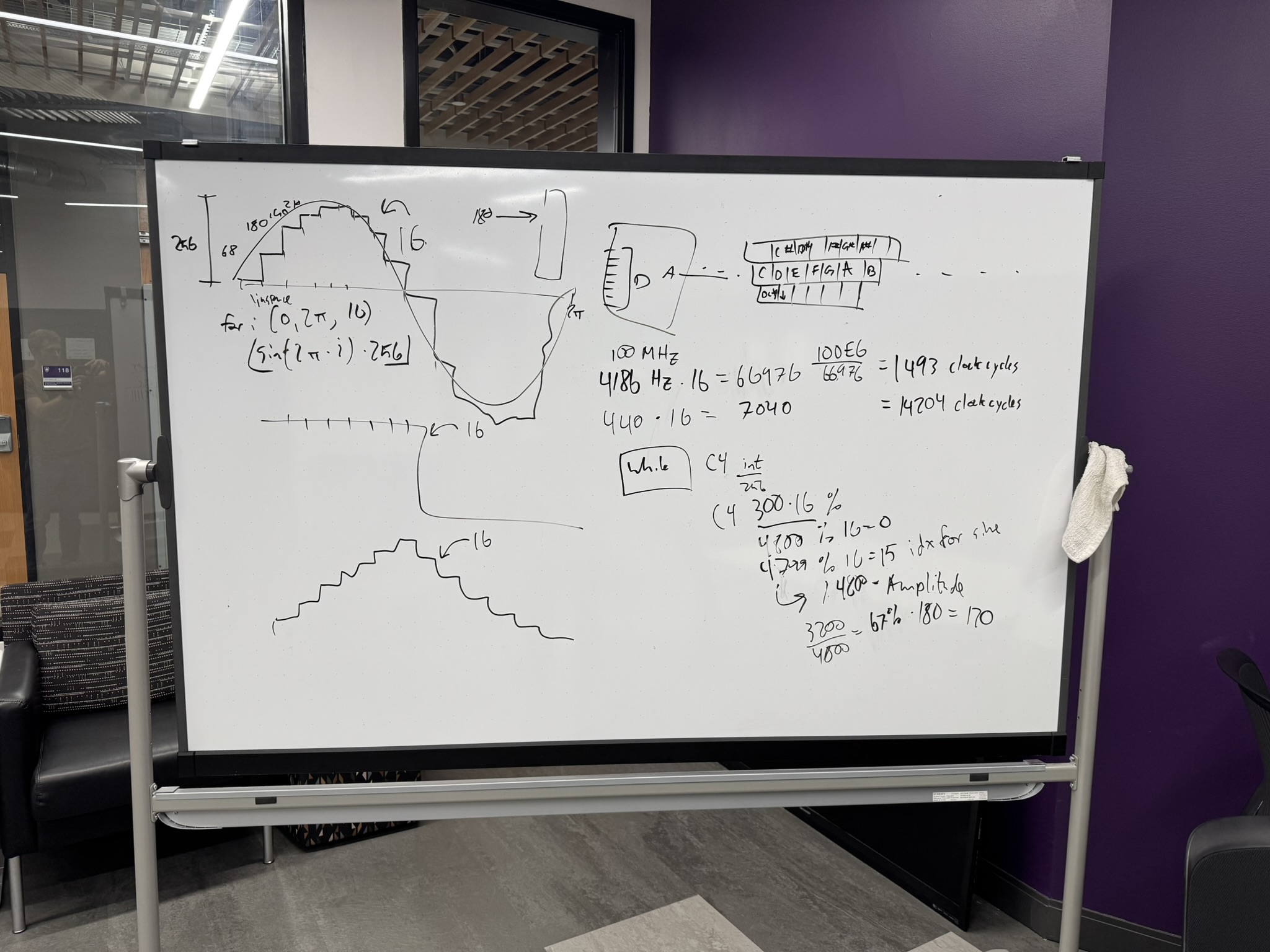
As you can so clearly see from our chicken scratches, we planned on sampling a sine wave 16 times throughout one revolution, then presenting those values as voltages to the amp, hopefully resulting in a beautiful and pure sine tone coming from the speakers.
Looking at the upper right portion of that dirty whiteboard you can see the rough outline of a computer's keyboard with the 12 notes of the chromatic scale placed on the home row keys, and the keys just above. I'm pretty sure this lines right up with the piano keyboard used by GarageBand for Mac. This original plan consisted of sending the corresponding ascii keys over serial to the FPGA and interpreting which note was to be played, and then generating the corresponding sine.
We met again and designed a system that would be able to play multiple notes at a time. As a general overview, there would be a block in the design that chooses what note would be played based on what is received from the serial connection. That block (aptly name the Logic block), would send signals to a certain number of wave generators, telling them whether they should be creating voltage waves and how fast to change voltage levels. This speed would define the frequency of the resulting wave, and after the waves are generated, the signals would be sent to a summer, which adds all of the waves together and makes a resulting combined waveform which is sent to the DAC. We figured that 8 voices of polyphony would fit on the FPGA, and allow you to play chords as complex as you could make with the keyboard piano.
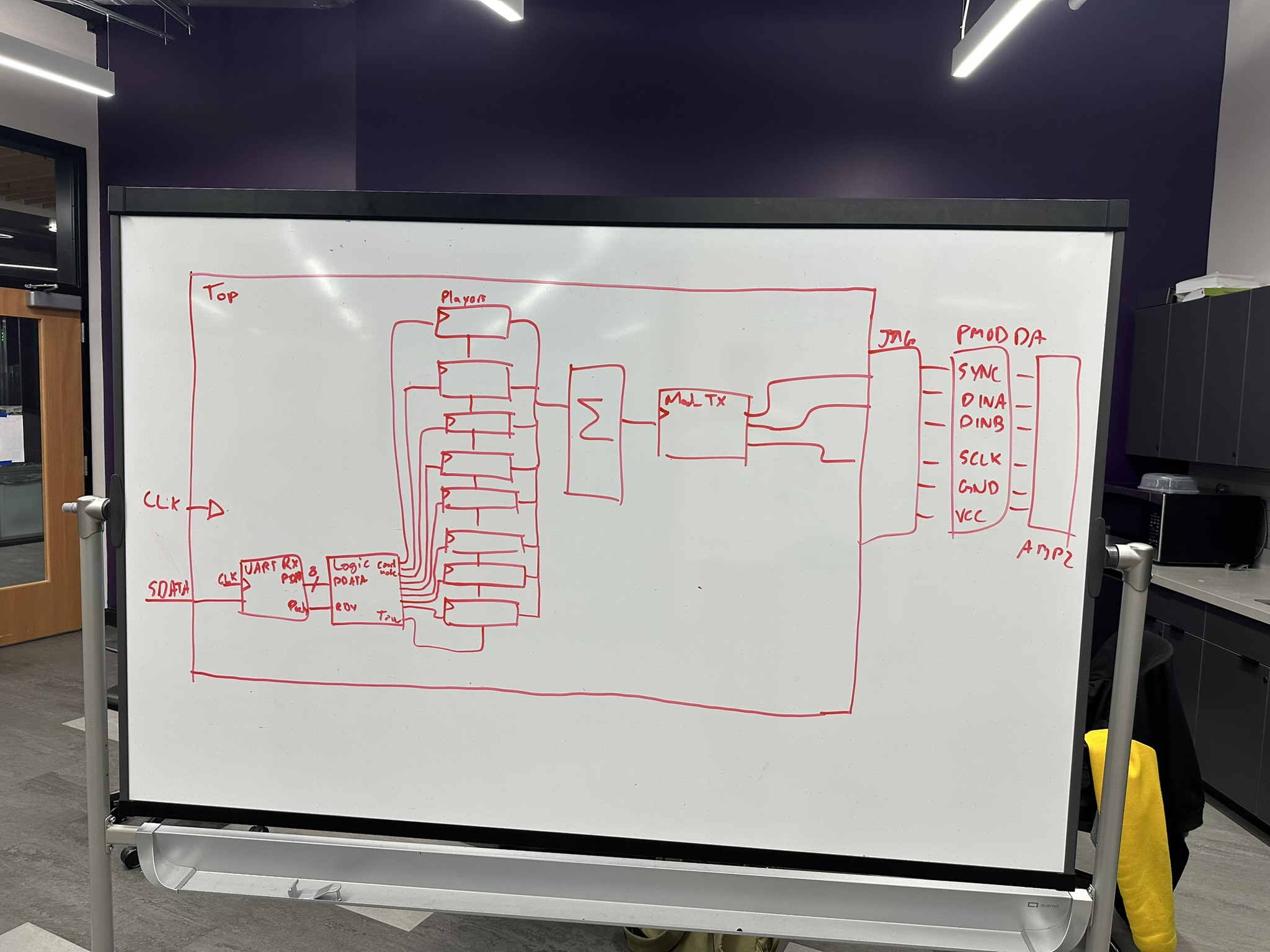
Without a way to detect if a note was lifted up, we decided that each note would just play for 1 second and decay. It wouldn't be as expressive as a real piano/synthesizer, but being able to play more than one note at a time was goal we were happy to meet.
The First Major Revision
Remember how I said this project suffered a lot from project creep? That starts now.
With this rough idea of a design in our heads, we adjourned for the day and kept brainstorming about how we would accomplish everything in VHDL. One morning I was exploring the MIDI spec, and I found the following circuit:
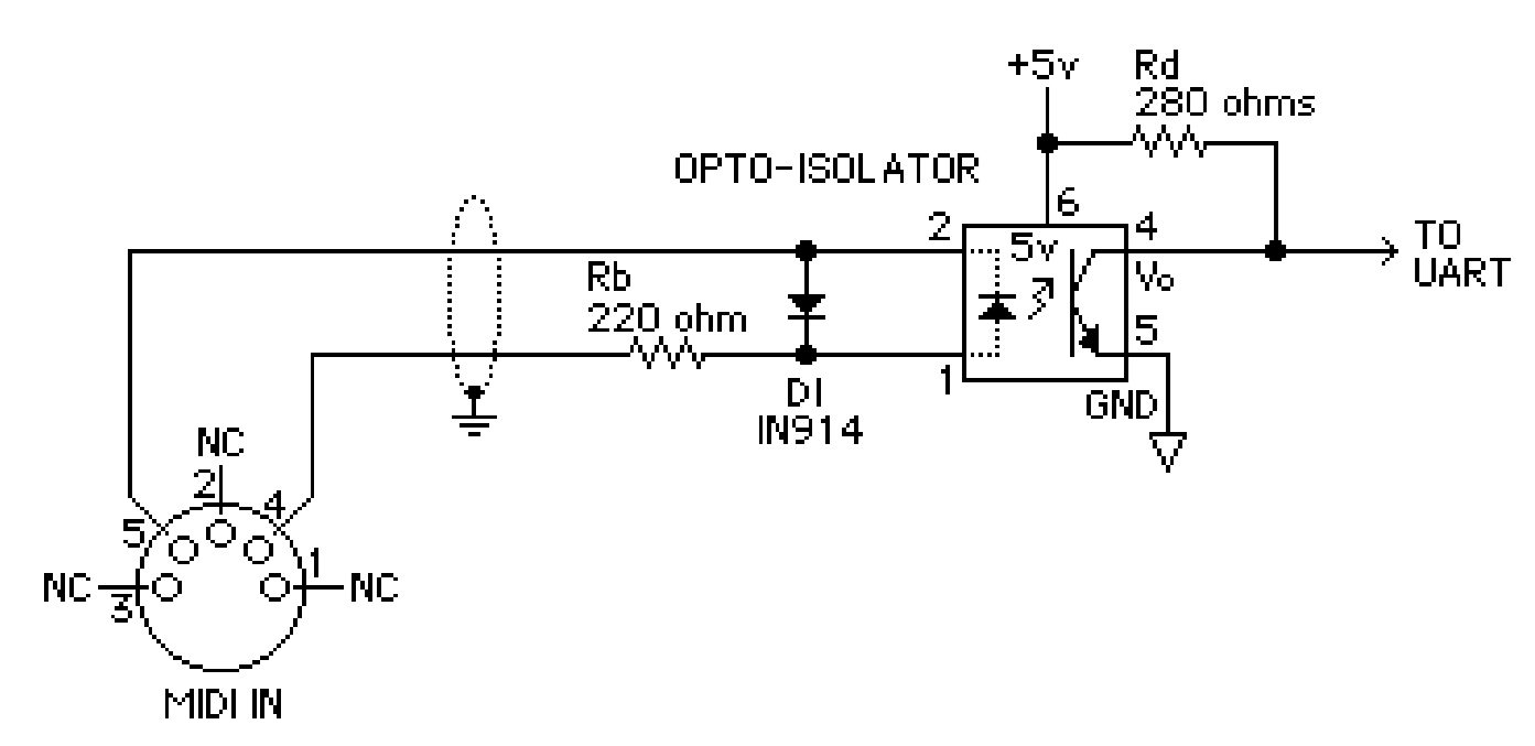
Notice on that far right side of the circuit that little arrow and annotation that says, "TO UART". I saw that and began to get excited. We've already made a UART Receiver in this class for these FPGAs, and I figured it wouldn't be too hard to just receive that UART signal as input and interpret MIDI data instead of just sending simple keystrokes from a hacky keyboard piano.
This in turn opened a world of possibilities for us. MIDI is the spec that 99% of the digital music world is built on, and would be plenty capable for the needs of our simple project. I showed this to my classmates one day after class adjourned and the ideas started flying.
"With this we could determine when the note is released, not only when it's pressed. Then it could act like a real piano."
"And I'm sure the MIDI protocol tells velocity sensitivity, right? Maybe we could incorporate that!"
"What about the control knobs? Maybe we could use a control knob from a MIDI controller to alter the character of the sound."
In the end, all of these things ended up becoming a reality.
The MIDI Protocol
Of course, this means that we would have to support the actual MIDI protocol. Neither I, nor any of my classmates, had worked with MIDI before, and we didn't know anything about it, but with about a week and a half before the project was due I impulse purchased a pack of MIDI female connectors and some cheap opto-isolators from Amazon.
With those on their way I started scouring the MIDI documentation. I learned that that opto-isolator circuit is a way to measure the digital information being transmitted over the MIDI cable while keeping the ground references between the MIDI cable and your digital device separate. It also turns out that MIDI operates at a strange baud rate, precisely 31.25 kBaud.
The messages sent over MIDI come in packets of 1, 2, or 3 bytes. The first byte of every packet is a status byte, and the following byte (or bytes) are data bytes which accompany that status byte.
For example, if the first byte is 90H — which corresponds to the NOTE ON command for MIDI channel 1 (address 0) — then the next two bytes should be interpreted as which note to turn on, and what the velocity of that note being pressed was. All of this information is neatly captured in Table II from the MIDI spec, which I've included below.
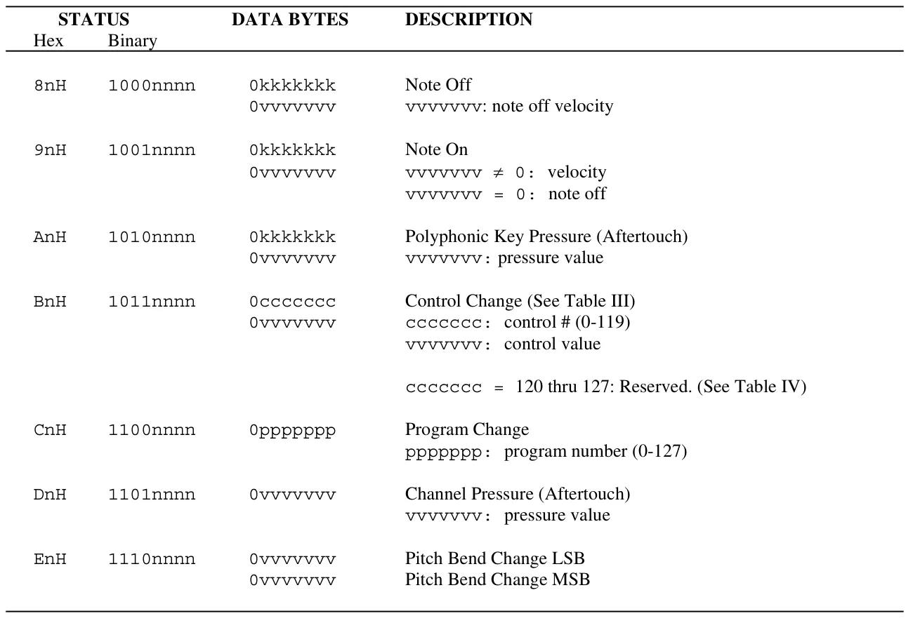
With this table in hand we have some real instruction when it comes to the MIDI protocol. As you will see later, I didn't perfectly implement the MIDI protocol on the FPGA. This was a design mistake, not any limitation of the hardware, but I forgot to include the support for stopping a note by sending the "Note On" message with a velocity of zero.
But before we can start parsing this data and controlling any sort of synthesizer, we have to first be able to receive a digital input from a MIDI device, and that means building the circuit from above. The day that the Amazon delivery truck delivered the components to my house, we went to the open lab on campus and built the circuit with an attempt to see if it worked. We plugged the input to one of the pins on the FPGA, pressed a key on a MIDI controller, but nothing happened. The project wasn't going to be as easy as we had hoped.
When building a digital system, or really any complex system, it's critical to know how every part of the system works. When getting everything to work together, you have to know how each part operates on its own. I took that circuit I had built to the open lab and connected an oscilloscope to the output which headed to the UART on my FPGA. What I saw wasn't pleasing. Instead of the nice crisp square-shaped signal from a digital transmission, I was met with a muddy signal showing slow rising and falling edges. It was too slow for reliable MIDI transmission and I went back to the MIDI documentation.
Well shoot. The set of cheap PC817 opto-isolators I purchased on a whim didn't seem to be fast enough. A quick review of the datasheet showed the rise and fall times to be around 6 μs typical, with max around 18 μs! These were way too slow for the MIDI protocol, but the Sharp PC 900 and other high speed opto-isolators showed 14 days shipping times, meaning that they would show up a week or so after the project was due. I should have seen this coming. The cheaper opto-isolators that we purchased from Amazon didn't have a connection to the base of the internal photo-transistor. Reading online I found that with an opto-isolator that provides a connection to the base, you can drop in a resistor between the gate and the collector of the transistor to increase the speed of the device. A reflection of the circuit shown in the MIDI spec has that exact resistor that I had read about, meaning that the components I had wouldn't be enough for the purposes of this circuit.
Beginning to lose hope I asked several of my professors if they knew of any extra opto-isolators lying around in a closet, just waiting to be used. While all helped me look, we weren't successful. After asking Dr. Gardner for any ideas where I might be able to find one, he pointed me to a box in the senior design lab. He said, "I get all sorts of companies sending me trial components and kits, and they usually end up in this box. I'd say there's about a 30-50% chance that this box has an opto-isolator in it that would fit your needs."
I began to be hopeful once again. I got on my knees and started filtering through hundreds of labelled ESD bags, hoping to find an opto-isolator. After about 45 minutes of searching through P-channel MOSFETs and random ICs, I found a bag that read "ACSL-6310-00TE High-speed Optocoupler". I was almost surprised when I found it, I spent the next hour struggling to solder these onto some SMD to 100 mm adapters so that we could prototype with these on our breadboards (it was my first time soldering SMD components, okay?).
I built the circuit using the new optocoupler and set up the oscilloscope from the open lab. After configuring for UART communication, I saw this when I pressed the middle a key on the MIDI keyboard.
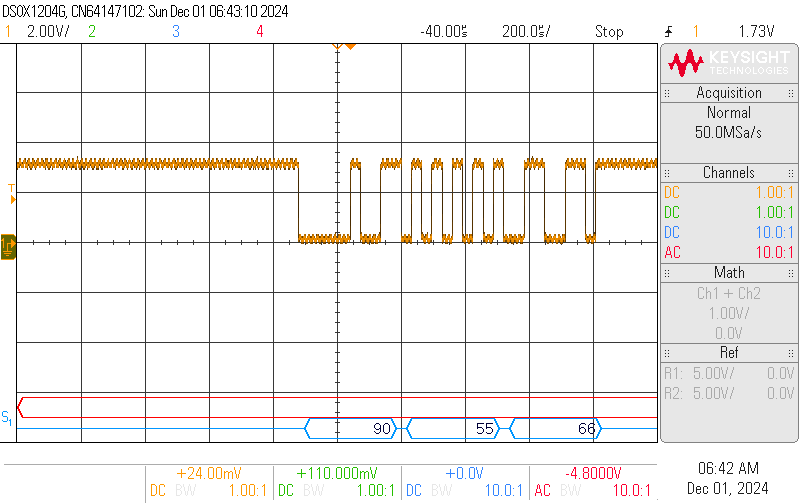
That line at the bottom showed exactly what I was hoping for. "0x90 0x55 0x66" is perfect MIDI protocol for "Note on, channel 1 (address 0), note G3, mezoforte".
Understanding MIDI in VHDL
With a reliable signal coming from the MIDI controller, we were finally able to start controlling the synthesizer. The state machine required to control the device (for the capabilities that we're planning to support) is actually rather simple.
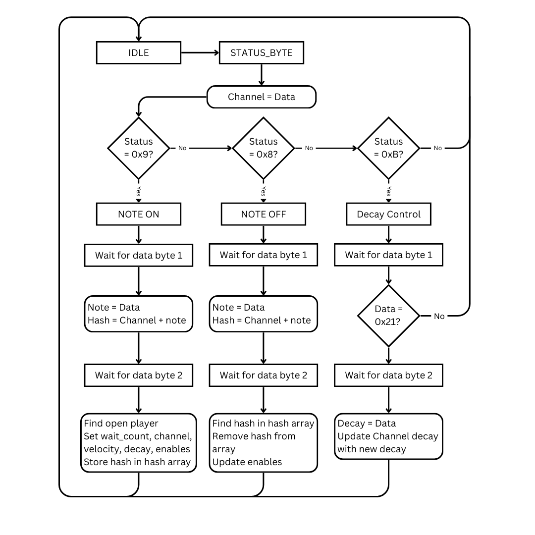
I've reduced some of the less important parts of the state machine for the sake of brevity, but the idea is straightforward. First, store the channel in a signal when a byte is received, if the status byte starts with a 9, you know we're receiving a NOTE ON signal. Otherwise if it's an 8, then we're receiving a NOTE OFF signal, and the last one that we check for is a B, which is the status byte for sending a control signal.
The largest discrepancy from this state machine and the operation of the actual FPGA is the lack of a couple extra states for the cases when we receive a status byte besides those three. The program simply waits for either one or two bytes and does nothing with them, depending on whether the status byte is one that receives one or two data bytes. Look back to the table mentioned above to see what I mean.
The trickiest problem to solve when building the MIDI logic receiver, was figuring out how to determine which signals to turn off when a given note is released. It's easy if you're only playing one note at a time. But, imagine you're playing notes C, E, and G, and then lift up only the note E while C and G remained pressed down. This state machine has to identify which note is being released and update the corresponding signals accordingly.
The solution I found was to store the channel and note being played together in a hash map that's as long as the number of wave generators — or possible simultaneous notes — there are. When that note is released, it can create that same hash from the given channel and note that was sent in the packet. With an identical hash to one of the notes, the program can search the array for the note that it needs to stop playing, and update the signals being sent to the wave generators accordingly. I'm sure this solution has been used several times before, but I was satisfied when I found it.
This article is already getting pretty long, so I'll have to make a part 2 to finish off the story. Thanks for getting this far and I hope you've enjoyed this journey as much as I have! Part 2 is coming soon.